The Z80 Microprocessor
Home
Background
History of CP/M
Architecture of CP/M
Using CP/M
Commands and the CCP
Programming with BDOS
The BIOS interface
The Z80 CPU
Architecture of the Z80
The Z80 instruction set
Software Tools
Installing an Emulator
Zip, ark, crunch, and urgh
Editors, Assemblers, Debuggers
Installing CP/M
Assembling a BIOS
Replacing the BDOS
Replacing the CCP
Reference
Memory Map
Data Structures
Glossary
History
In 1969 Intel were approached by a Japanese company called Busicom to produce chips for Busicom's electronic desktop calculator. Intel suggested that the calculator should be built around a single-chip generalized computing engine and thus was born the first microprocessor - the 4004. Although it was based on ideas from much larger mainframe and mini-computers the 4004 was cut down to fit onto a 16-pin chip, the largest that was available at the time, so that its data bus and address bus were each only 4-bits wide.
Intel went on to improve the design and produced the 4040 (an improved 4-bit design) the 8008 (the first 8-bit microprocessor) and then in 1974 the 8080. This last one turned out to be a very useful and popular design and was used in the first home computer, the Altair 8800, and CP/M.
In 1975 Federico Faggin who had had worked at Intel on the 4004 and its successors left the company and joined forces with Masatoshi Shima to form Zilog. At their new company Faggin and Shima designed a microprocessor that was compatible with Intel's 8080 (it ran all 78 instructions of the 8080 in exactly the same way that Intel's chip did) but had many more abilities (an extra 120 instructions, many more registers, simplified connection to hardware). Thus was born the mighty Z80!
The original Z80 was first released in July 1976. Since then newer versions have appeared with exactly the same architecture but running at higher speeds. The original Z80 ran with a clock rate of 2.5 MHz, the Z80A runs at 4MHz, the Z80B at 6MHz, and the Z80H at 8mhz.
Many companies produced machines based around Zilog's improved chip during the 1970's and 80's and because the chip could run 8080 code without needing any changes to the code the perfect choice of operating system was CP/M.
So, let's dive into the Z80 and see what's inside...
8-bit data, 16-bit addresses
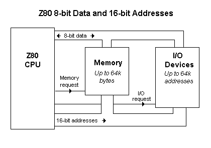
The Z80 uses 8-bit bytes which are stored in memory. These bytes contain both the program that the processor is executing and the data items that the program is working on. The processor uses 16-bit addresses to access these bytes, so there can be anything up to 64k (65536) bytes of memory. How much memory is actually available, and how much of it is read only (ROM) or random access (RAM) varies from one machine to another: in a simple controller there might be just 4k of ROM holding the program and 1k of RAM for the data items; in a large CP/M system you would find a full 64k of RAM.
The processor also uses a separate 64k of addresses for input and output devices. This I/O address space is only used by a few instructions (called, not surprisingly, IN and OUT) to send or receive bytes from I/O devices. The addresses for I/O instructions use the same wiring as the addresses for memory and the data bytes travel through the same wiring that is used for bytes in memory so the processor uses special control signals to differentiate between memory accesses and I/O operations. These control signals have to be decoded by I/O devices together with the addresses sent by the processor so that devices do not mistakenly respond to requests that were intended to read or write bytes in memory.
Programmer's Model
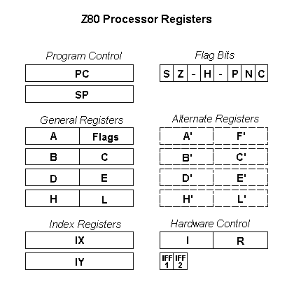
All programming of the Z80 revolves around its internal registers. These registers are used to control the flow of the program and to operate on data items. There are 16-bit registers inside the processor that address the program bytes in memory and there are 8-bit registers into which data bytes are loaded and then operated on. These 8-bit registers can also be combined in pairs to form 16-bit addresses and these addresses can be used to index data structures in memory that span several bytes.
Flow of Control Registers
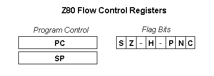
The Z80 uses a 16-bit program counter (PC) to hold the memory address of the next instruction to execute. This register gradually steps through memory as instructions are executed, but some instructions can alter it directly to cause the flow of the program to branch to a new location.
The Z80 also supports subroutines calls with a stack pointer (SP). When a subroutine is called the contents of PC are pushed into the memory location pointed to by SP and the stack pointer is decremented. When the subroutine has finished executing the stack pointer is incremented and the contents of PC popped back from the memory location. In this way calls to subroutines can be nested to any depth, as long as there is space to push the program counter into memory for each call.
The Z80 also contains flags to control the flow of a program. The flags are changed whenever an arithmetic operation is done and the flags can be tested one at a time by a jump instructions to change the flow of the program, depending on the state of the flag. The flags record the sign (S), zero (Z), half-carry (H), parity (P), and carry (C) of the result of the last arithmetic instruction and all of these can be tested by jump instructions. There is also a flag that records whether the last arithmetic operation was an addition or subtraction (N) which is only used to decimal arithmetic. These six flags are stored in a single byte (F) with bits 3 and 5 left unused.
8-bit Data Registers
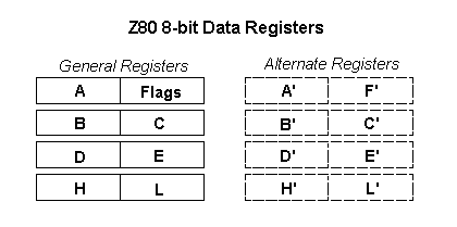
The Z80 processor contains 14 general purpose registers which can be used for holding and manipulating data bytes. Each of these registers is 8-bits wide and they are named A, B, C, D, E, H, L, A', B', C', D', E', H', L'.
As their names suggest the registers are divided into two sets. The first set are the registers A..L and the second set, called the alternate registers, are A'..L'. Most operations in the processor only work on the first set and the alternates just provide temporary space to save the contents of A..L. The Z80 has short instructions that exchange the contents of the working registers with the contents of the alternates. Of course, this temporary space could easily be allocated in memory but in applications where timing is critical it is much quicker to exchange the working registers and the alternates rather than having to save the working registers and then load new values from memory.
Once data has been loaded into the working registers the Z80 has a full range of arithmetic, logical, shifting, and rotating instructions to handle 8-bit bytes. The results of these operations generally end up in register A (the accumulator) from where they can be moved to other registers or saved back to memory locations.
In a few instructions the flags are treated as a single byte that is called the F register.
16-bit Address Registers
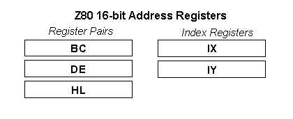
The Z80 contains two types of 16-bit addressing registers: register pairs and index registers.
Register pairs are formed from combinations of the 8-bit general purpose registers. The Z80 allows three combinations: registers B and C can be combined to form a 16-bit register that is called BC, registers D and E combined to form DE, and H and L combined to form HL.
These register pairs can be used to do some limited 16-bit arithmetic (addition, subtraction, increment, decrement) but generally they are used as pointers to data in memory. The instruction set is heavily biased towards using HL as a data pointer. Many arithmetic instructions can combine the accumulator A with the byte in memory that is pointed to by HL. In this way the byte in memory does not have to be loaded into a internal register before it is combined with the accumulator, saving instructions and register space.
The processor also contains two index registers (IX and IY) that can be used to address data in memory. These registers work very like the HL register pair in that many instructions can use a byte that is addressed by IX or IY as an operand. However, unlike HL, an offset is added to the value in the index register before addressing memory. This offset is contained in the instruction that is using IX or IY and it is an 8-bit value. This helps the programmer create fancy data structures in memory using an index register to point to the start of the structure and the 8-bit offset to select fields within the structure.
Hardware Registers
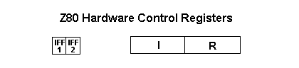
The Z80 also contains a few registers that let the user control its hardware in some simple ways.
Interrupts can be controlled with two flags (IFF.1 and IFF.2) and an 8-bit page pointer (I). The programmer can enable and disable some interrupts by setting and clearing IFF.1. When an interrupt does happen the current contents of IFF.1 are saved in IFF.2 and then IFF.1 is set so that further interrupts are disabled. When the program has finished handling the interrupt IFF.2 is copied back to IFF.1, restoring the flag to its original value.
Instruction Set
These links will take you to tables that describe the Z80 instructions in detail. They are broken down into groups of similar instructions:
8-bit Load and Store - Using the general purpose registers
16-bit Load and Store - Using register pairs, index registers, and the stack pointer
1-bit Arithmetic - Set a bit, Clear a bit, Test a bit
8-bit Arithmetic - Add, Subtract, And, Or, etc.
8-bit Shift and Rotate - Shift left, Shift right, Rotate, Insert carry bit, etc.
16-bit Arithmetic - Add, Subtract, Increment, Decrement
Flag Control - Set carry flag, Clear carry, Enable and Disable interrupts
Program Flow - Jump, Conditional jump, Call subroutine
I/O - Input a byte, Output a byte
Block Instructions - Move block of memory, Search a block of memory, Input or Output a block
3-Aug-98 22:38:42